NEW: Learning electronics? Ask your questions on the new Electronics Questions & Answers site hosted by CircuitLab.
Microcontroller Programming » Hacking an old school led display
|
January 18, 2011 by BStory 
|
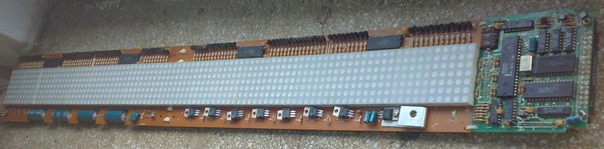
So I came across this display. Model number is AS-0216. It's run by an intel P8039AHL microcontroller(microprocessor maybe?). No datasheets to be found for anything inside except the intel chip. It has 19 5x7 led matrix blocks that get fed by four chips that are as far as I can tell shift registers of some kind. There are 11 wires going from/to the control board to the led circuits. To do away with the useless remote that runs it, I am going to gut the brains and hook up my atmega168.
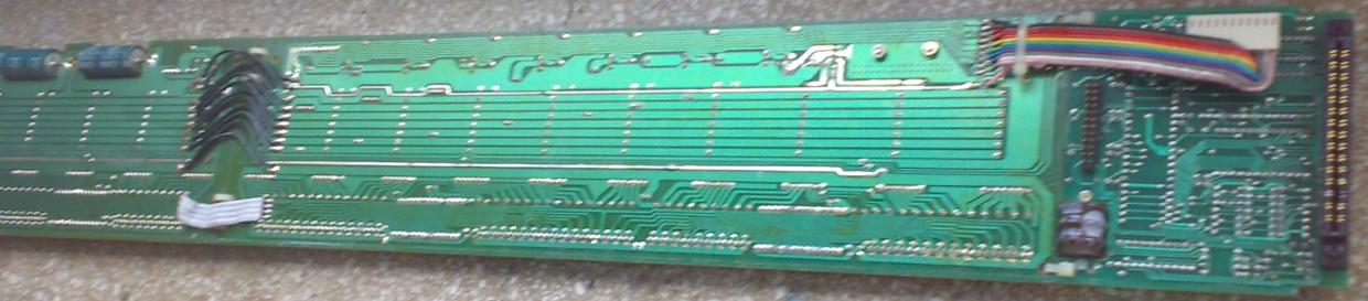
The green board is the control board.
The rainbow colored wires feed the data to the LEDs and power to the control board. I traced the... traces... and there are 7 wires for the rows and 4 other wires: pink - voltage supply to the control board. white - ground for control board. grey - clock line. purple - data line that goes to the first shift register only blue, green, yellow, orange, red, brown, and black for each of the 7 rows. The four 28 pin IC's seen at the top of the led modules are what I suspect to be some sort of shift registers. Printed on them is Chilong 3100110005 8738.
I think that what I need to do is hook each of the 7 rows to seperate pins, hook up the clock using PB5, and PB3 would be used for MOSI. I ran some sample code to see if the clock and data would actually get read by the mystery Chilong IC's and I got it to flood the screen with garbage. Progress!! Now I am stumped. I think I need to refresh 1 row at a time with new bits and all the examples code I find wants to send full characters at a time. Anyone willing to offer some hints on how to send bits across just 1 row of LEDs or tell me I'm over thinking it? |
|---|---|
|
January 19, 2011 by Rick_S 
|
I have to say, I'm soooo jealous :D. I've been looking for someone scrapping one of those displays for a while, and never seem to find one. That board should make for a great project and looks like lots of fun. Great job tracing out the lines on the board! The code for the LED Array tutorial does something similar to what you are looking for, it just breaks each row one step farther with even/odd columns. You could probably modify the code from that and spit it out to the shift registers. Rick |
|
January 21, 2011 by BStory
|
Thanks Rick for the words of encouragement. I have been plucking at this thing non stop for the couple days. I'm laid off for the winter what can I say ;) So far I haven't made any progress :( But that's if you don't count all the things I've tried that I now know don't work. I'm feeling pretty good about my understanding of SPI but help me make sure... If the registers are properly configured, you only need to assign data to SPDR and it pulses it out the MOSI line automatically at the assigned clock rate? I think I should probably get me a shift register that wasn't made in 1980. And one that I know is a shift register. It would sure be nice to run through this with some hardware that has documentation lol. I think I'm gonna have to shelf this project for a week or two until I get a better understanding of what the heck I am doing! :) I am thinking that there is a particular initialize bit pattern for these IC's. Somehow the LED array tutorial code unmodified and stock just as it is (using the same pins) produces at least enough flicker of the led screen to let me know that it's getting data sent. The problem I run into is when I install and run some chopped down basic SPI code I 1) get no output to the display and 2) can't get ledarray_master.c to work again until I disconnect the header, plug in the original control board, unplug and reconnect my uC. It's redonculous! My setup so far:
Each row will go through mosfets to ground when its pin is triggered. Only 4 rows now until I get some more artillery. It's funny, there's at least 95 mosfets in this display... I just want to borrow 3 of them lol. Anyway, that should prevent unwanted flicker... I think. Other than that it's a data line and a clock. Everything in the display gets power from the wall. Here is the code I have been testing with. I've been changing the code and sending all sorts of random data trying to get something. But nothing. That's why I'm starting to think there either must be some sort of initialize bit sequence, or I have no idea what I'm doing, or both: Any comments/ideas are greatly appreciated! -Bryan |
|
January 21, 2011 by 6ofhalfdozen |
this definately looks interesting.. dunno if you guys found it, but there is a polish forum talking about something with the same specs and part number.. I don't speak polish, but what google translate could do in a few minutes looks promising.. I don't have the time now to translate/read futher, but it might help some of you who are more motivated to sort this out. http://www.elektroda.pl/rtvforum/topic1584838.html |
|
January 21, 2011 by Rick_S
|
Another thing, if the display is powered separately, make sure it and your kit share a common ground otherwise the data pulses may not register properly. |
|
January 22, 2011 by Hexorg 
|
I used shift registers to bring to life my RGB LED Tetris. The only difference, my shift registers had latches to them, Which means that you could latch the row being displayed, and not worry about it, until it's time to show the next row. Are the Chilong 3100110005 8738 chips cascaded somehow? |
|
January 25, 2011 by BStory
|
It's been a crazy weekend and I didn't have a lot of time to work on this aside from verifying some connections. I traced back to see where the wires connect on the original control board. The wires for the rows connect from a CD4028BE (BCD to Decimal decoder) which connects from a SN74LS42N (4 line BCD to 10 line Decimal decoder.) The Clock Line comes from the PROG pin on the Intel P8039AHL chip. Studying the datasheet tells me that pin was designed to control the clock on an Intel 8243 I/O expander. Still not sure exactly what these chips are for but maybe I can at least figure out the timing for the chilong chips with this new found data. I'm with you on that Hexorg, I would think you could use each row separately as a latch. The 8738 chips are cascaded. There are 4 chips total U1, U2, U3, U4. Referring to the diagram labels of the chip above: data is sent from the control board to Signal In of the first chip in line (U1), each of the Q pins goes to a separate LED column. Q1 to column 1 through Q24 to column 24. Q24 also connects to Signal in of U21. I like pictures :)
All of the chips have similar paths with 2 exceptions. 1) U2 doesn't use Q24 so Q23 connects to U4 and 2) U4 Q24 terminates at the last LED column. |
|
February 28, 2011 by BStory
|
Baaahh ha haaa!!! Finally I got this thing figured out. I had to do some reverse engineering to figure out how the display works and why I couldn't get it to work for my MCU. I ordered a logic analyzer that is pretty awesome. Ok for 50 bucks it's really super awesome. Ok for waiting 30 days to get it it's only really awesome. Here is a screeny of my row1 pin action.
Problem 0.5: I'm a total noob to all this business. Problem 1: I needed mode 3 SPI. Clock needs to idle high or it won't show the output on these shift registers. Also I wanted to sample on the trailing edge while the clock was rising. Just 2 register settings. Who knew something so easy is so difficult. Problem 2: I couldn't figure out how to understand any of the led array code floating around in here. I think the multi rows and multi columns just threw too many i's and j's in my face lol. I started pretty much from scratch and learned a lot for it. On the plus side I'm really starting to understand all the community and example code I've been looking at. Problem 3: The display was giving me 5.2v which just wouldn't work for me. Too high i guess? Lucky for me it used a 7805 voltage reg so I put in one I scored from a dead AC adapter and that brought it down to a good 5.02v. Now I have it all sharing a common ground (thanks Rick for that advice). Here's the setup. There is an output pin for each of the 7 rows, the clock line, and the MISO. As far as I can tell, SPI will only accept 1 byte at a time(sending a 1 will still send a full 8 bits). I seriously considered trying some kind of bit bang method. The SPI port feeds 12 different 8 bit integers one by one to the shift registers. This is enough to fill the 95 columns. At 95 columns 1 bit falls off the end(I think). Anyway, when the 95 columns are set, data is latched to row1, then new data is shifted in that is latched to row2, and so on and back to row1 after the last row. You see solid light when the display is on even though it's actually cycling all of the rows using the same variables to fill in the data. The camera flash really didn't do the led brightness justice
I'm curious how many columns I could push a bit before there is flicker in the screen. I set it up to about 2000 uSecond delay between column refresh without any flicker. But yeah, it doesn't move yet. I'm just happy I got expected results with what I have. I would really appreciate if someone would look this over and give me some pointers. P.S. what is the trick to getting code to just show up right when you paste it in? |
|
February 28, 2011 by BStory
|
Most of you probably know this but make sure to put the break; line in all case statement or it will hit every case statement in the switch. That was 1 of many challenges I had in my debugging process. I tested my display at a higher transfer rate by adjusting the SPI clock registers and the best I could get was osc/8 at about 3000 uSecond ON delay with no flicker. I'm just gonna leave it at osc/128 until/if I add on the the end of this one. I think I'll work on getting this one working nicely first. |
|
March 09, 2011 by BStory
|
So I've been back and forth between this display and an electric bike motor control. I switch off when I get stumped like I am now lol. I put together a VB program that communicates through the serial port to the display but I haven't got the display to show characters properly just yet. I can see lines down the screen when I send data. I need some hints here. After writing all that code(above) I can finally kinda understand whats going on in the led array tutorial code and I think it's a lot better than what I slapped together so I want to use it. Except it holds data for the columns. Because how my shift registers are set up I have to update by rows. I'm trying to write some code that will convert the column data array to rows. This requires some bit manipulation and loops that are just confusing me. To break it down simply, say I have a row byte called row_data[0]. I need to get the columns data[0] through data[7]'s 0 bit into row_data[0]. data[8] through data[15]'s 0 bit would go to row_data[1]. And the second column would get data[]'s 1 bit. Here's what I've been working at. I don't think I'm even close yet. Too much to process so I'm hoping someone has a less confusing method :) |
|
March 10, 2011 by Noter 
|
Close but you need to mask the bit you want to move. Work it out doing 8 x 8 bytes and then expand. |
Please log in to post a reply.
|
Did you know that two resistors can be used to make a voltage divider? Learn more...
|


Copyright © 2013 by NerdKits, L.L.C.
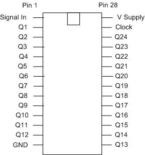 this pinout is based on my tracing and running tests so... yeah.


