NEW: Learning electronics? Ask your questions on the new Electronics Questions & Answers site hosted by CircuitLab.
Project Help and Ideas » Higher Resolution Large LED Display
|
April 05, 2011 by Singlecoilx3 
|
I own the Nerdkit and LED Array kit and have built all the projects (just by following the directions). I don't understand a lot about them other than I got them to work. I have a design in mind that I am trying to work on to have on display at my wedding reception (which is in July of this year). The idea is to have a large, higher resolution (maybe 10 x 100?), nicely finished led display that will hang on the wall and will scroll text. The text would be able to be sent via txt message from the people who are attending the reception (a note on the table that says something like- "send a text message to 555-1234 with a special message for the bride and groom to have it displayed on the led sign". I have combed the internet for a project that would be similar to this that I could tweak (minimally because of my understanding). I was given a tip from a friend to look for Arduino projects also since there is a lot of support for it online. I am not looking for someone to spend the hours working out all the details for me on this, but I wanted to create this thread to open discussion about this project and also for the possibility that someone else may want to do something similar in the future. Any comments welcome on this topic- I really want to finish this project to have at the reception. I think it would be really fun and different. No help is too small :) Thanks! |
|---|---|
|
April 05, 2011 by missle3944 
|
Hi Singlecoilx3 , For the recieving texts part - if i was u i would write a python script that reads texts sent from a cell phone to a google account or some sort of sms reader for your computer. Sryy if my typing is horrible, i just broke my wrist snowboarding a few days ago so i am trying to adjust. -missle3944 |
|
April 06, 2011 by Ralphxyz 
|
Hi Singlecoilx3, what a great idea!! Congratulations on your upcoming marriage. You should post a outline step by step of what you want to do. Have you looked at the Nerdkits expanded Array using three mcus. Possible you could stack six of them. Maybe using I2C port expanders and I2C Master/Slave mcu code could get you the processing power and large array. I really like your concept. In fact it fits in with my water curtain project. Ralph |
|
April 07, 2011 by Ralphxyz
|
Maybe Steven could help with you with the sms text messaging part. I've left a message for him in his thread. Ralph |
|
April 07, 2011 by Singlecoilx3
|
I am working on an outline and trying to research the best solution for receiving the text messages... google labs in gmail has a sms send/receive but it requires the gmail user start the conversation with each phone (will not work for this project). I have also come across many ways to SEND txt from a computer, but the receiving ones I have found are very limited, or like the google one- require the computer user initiate the sms conversation. Thanks for the input on this so far guys, and keep the ideas rolling :) Thanks Singlecoilx3 |
|
April 07, 2011 by Singlecoilx3
|
Here is what I've got for an outline so far...
|
|
April 07, 2011 by Noter 
|
Wow, that's a lot of stuff to complete by July! |
|
April 07, 2011 by Singlecoilx3
|
The large multiple panel LED display project already on the Nerdkits projects page allows for 'many' 5x20 panels (end to end) instead of a single 5x24 panel for the original LED display kit. I am wondering, as Ralphxyz mentioned, if the project could be easily adapted to have what would essentially be 10 panels, 5 across and 2 high. The programming change will most certainly have to change the way it displays text and scrolls since the letters would be 10x8 instead of 5x?. Can anyone with a good understanding of the multiple panel project speak to the difficulty of making this change? |
|
April 07, 2011 by Steven 
|
This is a really cool idea! I've been looking around and there are a couple services/companies that offer SMS functionality with .NET APIs. Essentially you want to write a quick .NET program that polls the service for new messages and puts them in a queue. Simply send the message over the serial port to your NerdKit. Here are some of those services: |
|
April 07, 2011 by Singlecoilx3
|
Wow Steven, that is some great information! I will take a look into those links and also look into using .NET. I am familiar with VB and Python (and some C) but never (knowingly) made anything with .NET Singlecoilx3 |
|
April 09, 2011 by Singlecoilx3
|
So after looking into .NET a little bit, it appears that I have been programming in a .NET environment (Microsoft Visual Basic 2010 Express)- correct me if I'm wrong. After looking into the links you suggested I was impressed with Esendex. Next on the agenda- learn to use APIs in my programs and then look over the Esendex API. |
|
April 10, 2011 by Singlecoilx3
|
I made up this sample display just to get a feel for the dimensions and look of the grid size I was planning. I definitely like the increased clarity of the letters. Below is an embedded version of the graphic I created. Here is a link to a larger version of the same thing. The grid itself was created using a free online grid creator I found at Incompetech.com
Singlecoilx3 |
|
April 12, 2011 by Singlecoilx3
|
I was doing some searches and found this program: SMS Enabler It looks like it can do exactly what I am looking for without paying a sms gateway/per message fee. It says it can be enabled to write the sms to an external file, database, forward to email, etc... It has a 45 day free trial (not sure if it is gimp-ware or fully functional) but as long as it works I think it would make my life easier. |
|
April 19, 2011 by Singlecoilx3
|
Just an update- I was not able to get SMS Enabler to work with the phone I have. But... I have been working with an Android developer who has an app in the market called 'SMS2PC'. He is currently writing an API that is compatible with vb.net that I'll be able to use for the app I am going to write. If he makes it freely available I will share it with you all. Next... As far as the physical construction goes- I have a friend with a CNC router. He is going to cut out the holes in the front plate so that the LEDs will be uniform and will fit snugly into the holes. This will also help with the angle the LEDs will be facing to cut down on issues that are related to viewing angle. I plan on using a 30deg viewing angle LED instead of the 15 deg LEDs that came with the LED Array kit from the Nertkits folks. This should also help with the problems I had with my original array in regards to the viewing angle. Any suggestions on the construction of the sign and the 'box' that will contain it are welcome (I would rather think about it before I start building than after...) Next... Okay- So here is going to be the largest struggle for me: designing the circuits. As I mentioned on my first post, I was able to get all the projects to work by following the directions in the kits, but my understanding of microcontrollers and circuit design is very limited. I definitely welcome any info, suggestions, calculations, explanations, links, comments, etc... to help with this part. Thank you in advance :) Thanks again for all the great information so far. I think things are on track to come together in time. I will continue to post updates and pictures along the way to keep you all up on my progress. Is anyone else working on a similar project right now? Does Humberto or Mike want to chime in with their take/suggestions on this project? :) Thanks! Singlecoilx3 |
|
April 19, 2011 by Singlecoilx3
|
My friend did up some renders in Solidworks: Front View:
Back View:
Game Room (not to scale)
Here are the measurments: ---- LED Board ---- LED board length = 1020 millimeters = 3.34645669 feet = 40.1574803 inches LED board hight = 120 millimeters = 0.393700787 feet = 4.72440945 inches LED board thickness = 1/8 inch LED spacing is 10mm (0.393700787 inches) from center to center in both directions ---- Oak Box ---- Thickness = 0.5" Depth = 3.0" |
|
April 20, 2011 by Singlecoilx3
|
Question: Which would work better for this project- I2C or SPI? The NK folks used SPI in the multi-panel array but I have also been reading up on I2C after Ralphxyz's suggestion. Any opinions on this? |
|
April 20, 2011 by Singlecoilx3
|
(continued) ...or shift registers? |
|
April 20, 2011 by Noter
|
Either one will work fine but I2C will require only 2 pins while SPI will require 3 plus 1 to select each slave in turn. I2C also has a broadcast capability to send the same cmd/msg to all the slaves at once. Don't know if you could use that or not. How many slaves do you plan to have? |
|
April 21, 2011 by Singlecoilx3
|
10 slaves |
|
April 21, 2011 by Singlecoilx3
|
Oh, by the way- I couldn't find any good 10x8 fonts online that I could use for my font index so I did an Google search and found this nifty website that lets you create your own font: http://fontstruct.com. The font file itself isn't important to me, but being able to design the letters in a nifty grid definitely saved me some time and effort. Just figured I would post it in case it helps someone else. Singlecoilx3 |
|
April 21, 2011 by Singlecoilx3
|
a* Google seach |
|
April 21, 2011 by Noter
|
In that case I would definately go with I2C over SPI or shift registers. Get the latest version of master/slave code (TWI.c & TWI.h) near the bottom of http://www.nerdkits.com/forum/thread/1423/. I can also provide sample slave side code if you need it. |
|
April 22, 2011 by Singlecoilx3
|
Thank you for posting that link Noter. I will check it out tomorrow and let you know if I want to take you up on that offer. Singlecoilx3 |
|
April 22, 2011 by Singlecoilx3
|
I just wanted to post this link for anyone who may be doing a similar project. As I posted above, I used fontstruct.com to create a font template for this project. Here is a link to the 10x8 font I created in case you would like to use it. Note- the website does require you to login in order to download or 'clone' the font. I would recommend 'cloning' the font so you can look at each letter within the grid-view to make it easier to see for creating the font template for your project (assuming you are using the method the NK folks do). Cheers, Singlecoilx3 |
|
April 22, 2011 by Noter
|
Thanks for the font. I grabbed a copy and will use it one of the days I'm sure. Ralph's water curtain needs an 8 bit font too so he may use it even sooner. |
|
April 22, 2011 by Ralphxyz
|
Absolutely, this is great. I haven't looked at the font setup yet, I wonder if I'll be able to do a 32bit font? I suppose I should just try making a font to find out. I had gotten some transparency sheets that I was going to use as a overlay to take off the bit pattern but it looks like this font maker might save me the step. Thanks for the link, Ralph |
|
April 22, 2011 by Ralphxyz
|
Well I tried the font program. It is really nice and there have been some fantastic fonts made using it. But how would one use a True Type Font (.ttf) in conjunction with a Nerdkit? I was hoping it would make a bit pattern text file which I can see using on the mcu. The .ttf is essentially a compiled font, good for pcs with a True Type driver but that is not available on a AVR. Am I missing something? Ralph |
|
April 22, 2011 by Singlecoilx3
|
Ralph I would recommend forgetting about the ttf file and just use the letter editor on the website just as a visual aid for creating your own ascii font file similar to the way the NK guys did. I was looking at this as a tool to get the letters to look correct. For example: I will have the "A" open on one screen and notepad open on the other while I 'map' the letter in notepad. Check out the NK font.txt file to see how they implemented it. It looks like the first line is the letter name, the second line is the width (which in my font will always be 8) and the following lines are the map of the letters. Hope this helps... I will be creating a map like this for myself, so I may just post a link to the map also since this may save you from doing the same work) Singlexoilx3 |
|
April 22, 2011 by Ralphxyz
|
Hi Singlexoilx3, can I just call you George? Yeah that is what I was coming up with also, that will be a help. I can definitely use it to get a take-off of the bit composition. Thanks again, Ralph |
|
April 22, 2011 by Singlecoilx3
|
Ralph, You may call me George if you like, I will be more likely to respond to Eric though :) |
|
April 22, 2011 by Ralphxyz
|
Of course just to make sure I do not have any free time I am working on trying to develop a program to scan a image and to produce a text file from the scan. "We", well I supervised the programmers that actually did the work, had to develop signature capture algorithms for hand held devices 15 - 20 years ago and the programmer once the program was done said it was really simple to implement. He explained the steps to me but I never needed to do anything with the knowledge so it just sorta evaporated from my mind. I want to use a tablet pc as a picture box and capture the co-ordinates of where a mark is made on the screen. In theory it sounds simple, and my programer described it as simple to implement (using C++) now I need to figure it out. Ralph |
|
April 22, 2011 by Singlecoilx3
|
I am getting ready to purchase the MCUs from the NK store. I was wondering if the ATmega328P would be better for this project? My concern was making sure people that sent a long(ish) text message would not have the message capped because of having less memory on the chip. I don't know if having more memory on the chip would have any affect on this or not- or if it is only more memory that my programs can be stored in. Sincerely, Confused in Oregon Eric |
|
April 22, 2011 by Noter
|
It's all of the above. The 328 has twice the flash, eeprom, and ram. I always buy the 328P although I have only one project so far that has actually exceeded 16k in flash requirement. The only 168 I have is the one that came with my original nerdkit. So, I think you will be fine with the ATmega168's but maybe buy one 328P to use as your master just in case. Or maybe you want to buy a ~$25 USBISP type programmer off eBay and get plain 328P mcu's (without the bootloader) for about 1/2 the price. Then you can put the bootloader on them yourself if you wish as well as set fuses to use the internal 8mhz clock which has no requirement for an external crystal. Rick is the expert on those little programmers and can probably point you to the best one to get. |
|
April 22, 2011 by Singlecoilx3
|
Thanks for the info Noter. I like the idea of being able to program the bootloader myself. I will see if Rick can give me a hand picking one of those out. I will probably just go with all 328s since they are still pretty cheap. Have you any experience using the internal clock? Have you seen any problems come up compaired to external crystals? I guess if I have issues with it I can just use the external one that came with the original NK. |
|
April 22, 2011 by Noter
|
Yes, I use the internal clock quite a bit. I have a real time clock that runs timer2 asynchronously with a 32767hz watch crystal on XTAL1 and XTAL2 so the only choice for that configuration is using the internal clock. And I have another project where I just need all the pins for I/O so I use the internal clock there too. More general, if the 8mhz interal clock will do the trick I use it just to avoid the need for an external crystal. The only issue I have had is some of the baud settings for the USART have an error value that is greater than 3% so they won't work with all PC's (especially mine it seems). You can see the baud error values for various clock rates on pp 200-201 of the ATmega328P datasheet. As you know this is no longer a problem for me since implementing the FT232R USB interface yesterday which lets me run at 250K baud while using the 8mhz internal clock. There exist other requirements between masters and slaves with relation to their clock rates and bitrates used but none of these have been an issue for me with the 8mhz clock. I think they are more of an issue for very low slave clock rates of less than 1.5mhz. |
|
April 22, 2011 by Noter
|
By the way, there is risk in messing with the clock rates and fuses. If you accidently clear the reset enabled bit and burn the fuse, that chip is done until you get a high voltage programmer. I have to admit that I have a little bag of mcu's that someday I will recover. Best to buy more mcu's than you need so you'll have a few spares ... |
|
April 22, 2011 by Ralphxyz
|
and then even though you can save a little money it is nice to support the Nerdkits guys by purchasing from their store. I can and do save by buying from DigiKey or Mouser but I'll also make some purchases from the Nerdkits store. Their support here in the forums or by email has to be worth something. Ralph |
|
April 23, 2011 by Singlecoilx3
|
Found Rick's post about it here: http://www.nerdkits.com/forum/thread/1358/ Thanks Rick :) |
|
April 23, 2011 by Rick_S 
|
No Problem... Any questions, just ask. Rick |
|
April 28, 2011 by Singlecoilx3
|
Update: I placed an order today for fifteen ATMEGA328P-PU (of which I plan to use 11 for this project). As of the time of my order I was able to buy them from Mouser Electronics for $3.31/ea + about $7 for shipping. This price included a quantity discount of 10+ pieces. The 1+ piece price right was $4.28/ea. Because these chips do not come with the bootloader like the ones you can purchase in the Nerdkits Store, I also needed to purchase a USBISP Programmer to program the bootloader into each MCU. I took Rick's advice and purchased the one from Fun4Diy.com. I ended up getting two of them, but I paid $8.50 for each unit + $2.50 for s/h. It came as a kit (see pictures on the website) including all the parts needed to build it as well as a schematic diagram. I did decide to go with the SPI bus as opposed to I2C or shift registers, etc.. on the advice of an engineer I work with that I discussed the project with- as well as the availability of the NK source code for the multi panel sign they made in hopes that I can use parts of it and tweak it for my project. I checked with the people at the wedding reception hall we booked and there is no wifi/internet access available in the hall :( :( :( . This means that the SMS > PC solution I go with must not involve the internet. I have an Android-based phone and have been corresponding with the developer of the SMS2PC app in the android market. He said that he may be able to write a simple API that is compatible with VB.NET that I can use to import the incoming SMS messages to a database where they will be usable for my project. I am quite nervous about this as this is the only potential solution I have that doesn't involve internet access and it is still not guaranteed that he will be able to get the API to me, and/or get it to me in enough time for me to get it worked into my project. Any suggestions for other non-internet based solutions are definitely welcome as this is the part that has got me the most stressed :-|. The physical construction of the oak project enclosure and the front face with the holes for the 1000 LEDs should be getting underway soon. As I mentioned in a previous post, I have a friend who will be making the front face with his CNC router, and once that is finished I can get started on the oak project enclosure. I hope to have a circuit diagram up soon. I had planned on having a slave for each 10x10 section of the grid. I haven't actually sat down to really look at this to see if it would indeed be the case. Any discussion on this is also welcome as I know there are many of you with much more experience in circuit design than I have. Thanks again to all who have contributed so far to making this idea a reality. I am still very excited to get this project off the ground and see it in action. Cheers, Singlecoilx3 (Eric) |
|
April 28, 2011 by Ralphxyz
|
Eric, you might drive by the reception hall to see if there is WIFI. The hall might not have wifi but possible a carrier or someone might. Ralph |
|
April 28, 2011 by bretm 
|
16x32 stackable LED matrix. Might save some time. |
|
April 28, 2011 by Singlecoilx3
|
@Ralph- That is a good idea, it is only 2 mins from my house anyway... @Bretm- thanks for posting the link. I wouldn't mind using some ready-made panels like that in a future project but I am set on the homemade variety this go around. I also appreciate the idea since it potentially could save a lot of time which is always nice when a project has a deadline. Eric |
|
May 01, 2011 by Singlecoilx3
|
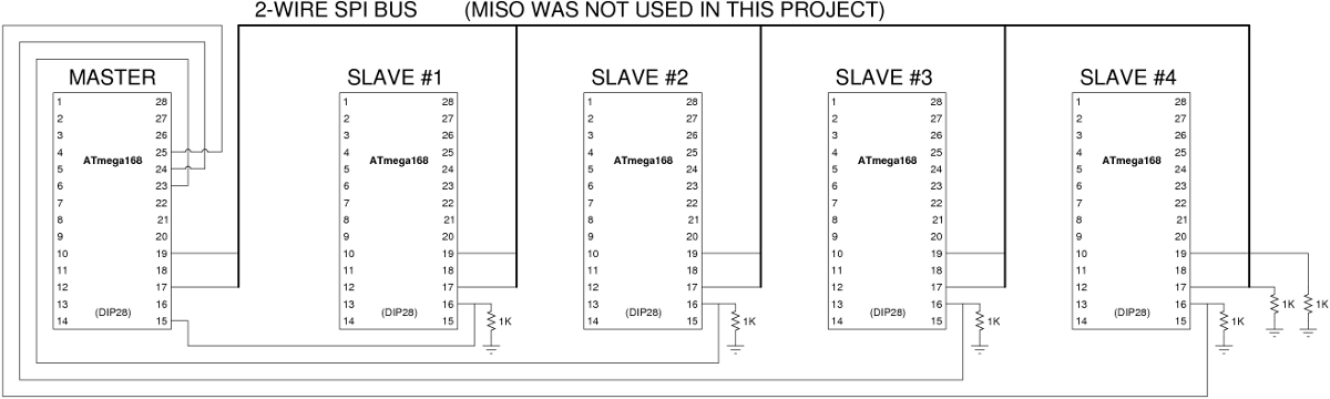
I am knees deep in the schematic drawing process now, and I've run into something I am unsure about. I am using SPI and I have 1 Master and 10 slaves. I have all the chips tied together on pin17 for MOSI, all the chips tied together on pin19 for SCK, and I now need to figure out WHICH PINS I CAN USE ON THE MASTER FOR SS LINES that will be routed to pin16 on each of the slaves. I see on the NK guys' multi-panel project they are using pins 15, 23, 24, and 25:
What other ones are legal? Bonus points if you can explain why, or point me to a page in the datasheet or a link/post/whatever that explains it. Thanks! Single |
|
May 01, 2011 by Ralphxyz
|
I think you can use any pin that you can tie high/low for CS (chip select). So if you can make a pin high than you can use it as chip select. Ralph |
|
May 01, 2011 by Noter
|
If you master is the regular nerdkit with the led display and crystal, you won't have enough pins available to select all your slaves unless you use the internal oscillator to free up PB6 and PB7. With the external crystal installed you have only 8 pins available - PB1, PB2, PC0, PC1, PC2, PC3, PC4, and PC5. |
|
May 01, 2011 by Singlecoilx3
|
Would this not work?
PB6 and PB7 are still open for the external osc... Did I use some pins that are off limits, or did I forget about something else? |
|
May 01, 2011 by Singlecoilx3
|
...or was the assumption made that I would be controlling some of the LEDs with the master also? Eric |
|
May 01, 2011 by Noter
|
Sure that will work. I forgot you are going to program using the SPI instead of serial/usb. Isn't PD2 used by the LCD or are you not going to use the LCD? You can use PB2 as a regular I/O pin on the master because it is not needed for SPI. You don't need any of the resistors to GND. |
|
May 03, 2011 by Singlecoilx3
|
I Got the atmega328p chips in yesterday, going to try and follow Rick's instructions for copying the bootloader to the chips tonight. Looking into the type of material I want to use for the front face of the sign (the piece with the holes in it). So far it looks like Black ABS Sheet is the leader in this race. Here is an example of what I am looking at. Does anyone have any experience with ABS? Is it usually shiny or flat looking? I got an email from the SMS API guy and he says he is still working on the SMS2PC API for VB.net that I plan to use. Things are pretty well on track I think for the deadline (July 2nd). I think the biggest struggle for me is going to be the microcontroller programming. I will have to start combing through the NK guys' code and see what I can pick out for my project. Singlecoilx3 (Eric) |
|
May 08, 2011 by Singlecoilx3
|
I've run into some problems with installing the bootloader on the chips. I am currently working with Rick to try and get it worked out. I just received my order for some small solderable perf-boards from WestFloridaComponents.com that I am going to use for the panels (1 per slave/panel and 1 for the master MCU). The holes are perfect spacing for the MCUs with solderable copper rings on one side. If I am smart- I will socket the MCUs on each perf board to allow for changes to the MCU code (and debugging). I also just ordered the Black ABS Sheet - 1/8" that I am going to use for the front face with the holes for the LEDs. I got it from TapPlastics.com. It is being delivered to my friend with the CNC router who will cut the panel and holes and then mail it to me. Once the exact size of the panel has been figured out (we had to change it a tiny bit because of the size limits of his CNC router) I will be purchasing the 1/2" oak for the project enclosure. This will be a fun part of the project, as I love woodworking. I need to order the LEDs- (the ones I want are EXPENSIVE, sad day...) The trick here is getting a wide enough viewing angle (I am getting 30deg) and a nice high brightness rating. Oh- and having low power consumption doesn't hurt too... Now that I have some of the various balls rolling I am going to start working on the software side of things. On this I shall certainly need some luck :) Singlecoilx3 (Eric) |
|
May 12, 2011 by Singlecoilx3
|
Update- I got the problem with copying the bootloader figured out (thanks to Rick for all the help). Now working on the C code for the master/slaves. |
|
May 20, 2011 by Singlecoilx3
|
I am LED shopping and would like to get some clarification on the luminous intensity rating, 'mcd' The NK guys advised me that the LED array kit comes with these LEDs which, according to the seller's website, have a luminous intensity of 2200-2500 mcd. Some LEDs that we use on a product at my job are these ones which, according to the seller's website have a luminous intensity of 15 mcd. Since these ones are pretty stinkin' bright, I have a hard time believing they are only 15 mcd. OR- maybe it is that the other ones aren't actually 2200-2500 mcd.... OOORRR... some of the properties are different enough to rate it so much lower- viewing angle (20 vs 30), diffused lense (yes vs no), etc... If I understand mcd correctly- 1 mcd is roughly equal to 1/1000th of 1 candlepower. So this means that this LED is only about 15/1000ths of the brightness of a candle?? That hardly seams right when the LEDs I got with my NK Array Kit were hardly any brighter than those, yet claiming 2.2 - 2.5 candlepower?? Thanks for any 'light' you can shed on this for me, <grin> btw- the ones I were looking to buy for my Large LED Array project when I became perplexed by this oddity were these ones. I need over 1000 of them so it would be 5.4 cents each if I go with these. They are also claiming to be 15 mcd, which is the reason for my hesitation, and this post. Thanks for the help! Singlecoilx3 (Eric) |
|
May 20, 2011 by Singlecoilx3
|
....... how do these ones look? Illumination Color: Red Lens Color/Style: Diffused Operating Voltage: 1.85 V Wavelength: 640 nm Luminous Intensity: 400 mcd Operating Current: 20 mA Viewing Angle: 30 deg Lens Shape: Dome Mounting Style: Through Hole Package / Case: T-1 3/4 |
|
May 20, 2011 by bretm
|
Since you're lighting up so many of them, I'd consider a low-power model. I don't know about brightness, though. That's certainly confusing. This one is 4.5 cents at 20mcd but draws only 2mA current: WP7104LSRD They're T-1 size, so I don't know if they're big enough for you. |
|
May 20, 2011 by bretm
|
(1000 LEDs at 20mA is 20 amps) |
|
May 23, 2011 by jabelch 
|
It looks like you are already going a different direction, but have you heard of or looked into Google Voice? You can choose a phone number in any area code that links to your google e-mail. I get texts through my e-mail all the time, (which is useful when you don't have access to your phone). If you want me to send you an invite, let me know. As for no wifi, many phone carriers offer a data plan through smart phones that allows you to tether your phone's internet to your laptop/pc. It may be more than most are willing to pay on a regular basis, but I think it would be worth it for a wedding :) Also, you may want to ask friends and family if any of them already have a tether/data plan and are willing to share it for the night. Josh |
|
May 23, 2011 by jabelch
|
Also, have you looked at abcTronics? I saw that NerdKits buys from them, and 1000 Red LEDs would cost $29.99... that's pretty good. These ones are still rated at 20mA, but show an output of 2700 - 3000 mcd (3mm model). I don't know enough about driving LEDs yet, but perhaps driving it at a lower amperage will still yield decent light output. Plus, unless you plan to have every LED on at full strength at the same time you won't hit 20 amps (which, if I'm not mistaken, would fry your controllers) |
|
May 29, 2011 by Singlecoilx3
|
Thanks for the good ideas folks. I did end up going with ABCTronics. The LEDs they offer aren't exactly what I was wanting (somewhat narrow viewing angle, non-diffused) but they are very bright and very cheap. Plus, if I really want to, I can use some fine grit sandpaper to diffuse them a bit. It cost me a total of $51.97 for 1200 red 5mm LEDs shipped to Oregon. I have been so busy in the last week or so, I got laid off this past week and haven't had much time to work on this. I have been going through the nerdkit guides trying to better understand the programming for the MCUs and combing through the LED Array code and the multiple panel SPI master/slave code to try and figure out what modifications I will need to make. At this point I know that I will obviously need to change the pin assignments to match mine. Also, since I have 10 rows (for each 10x10 'panel') I will need to have my array be 2 bytes per column to hold my 10 rows and be wasting 6 bits per column, instead of the single byte 5 row column in the original nerdkit project (which wastes 3 bits per column). As this is my first time really creating my own project with the NK instead of just following the directions on their creations step by step, I appreciate any tips, suggestions, or help with this part of it :) Thanks! Singlecoil (Eric) |
|
June 02, 2011 by Singlecoilx3
|
Wedding is 30 days from today!! Running a bit behind schedule... I am definitely going to need some help with the C code part of this project. I will post the modifications to the spi_master.c and spi_slave.c files soon if someone wouldn't mind checking out the code and pointing out some things I am not doing correctly (get your red inkpens ready!) Thanks in advance. On another note, I just purchased the last of the parts I need for this project (with the only exception being the wood for the outside frame). In case it helps anyone working on a similar project- here is what I got: a 500ft spool of this 24 gauge solid hookup wire from bulkwire.com ($20.29 + $7.90 s/h = $28.19) I'm sure I could have done with much less, but I wanted to get enough to have around for more projects. 15 (4 extra) of these STMicroelectronics L7805CV 5V voltage regulators. I'm not sure I am really going to need more than 1, but now I will have them if I need them. 15 (4 extra) of these 0.1uF 50volt capacitors. 15 (4 extra) of these 14.7456MHz Crystals (FOX / FOXSLF/147-20). Thanks! Eric |
|
June 02, 2011 by Singlecoilx3
|
here is the master code that I have edited so far... I can't test it yet because I am waiting for the stuff I ordered to come in the mail. See any issues so far? I don't understand a lot of this code so I am sure there are a lot of things wrong for changing it to a 10x100 display. Modified Master Code: |
|
June 28, 2011 by Rick_S
|
Eric, I haven't seen any project updates since the beginning of the month. July is nearing and I was wondering if the project came together, is close to coming together, or didn't work out as you planned. It seemed to be such a interesting use for the kit I was hoping to see it come to be. Hope all is well with you and your future wife, (and the project! Rick |
|
July 08, 2011 by Rick_S
|
Well Eric, Are you Married?? I hope everything was successful I know it's been less than a week since the day so you are probabaly on your honeymoon. Hopefully you'll see this when you get back. Best wishes for a long and happy marriage. Rick |
Please log in to post a reply.
|
Did you know that the microcontroller's crystal oscillator can be used to keep accurate time? Learn more...
|


Copyright © 2013 by NerdKits, L.L.C.


 ) - I know the days before the wedding can get somewhat hectic, and your's is only 4 days away.
