NEW: Learning electronics? Ask your questions on the new Electronics Questions & Answers site hosted by CircuitLab.
Everything Else » Look at this programmer PCB I made :D
|
August 22, 2012 by Pew446 |
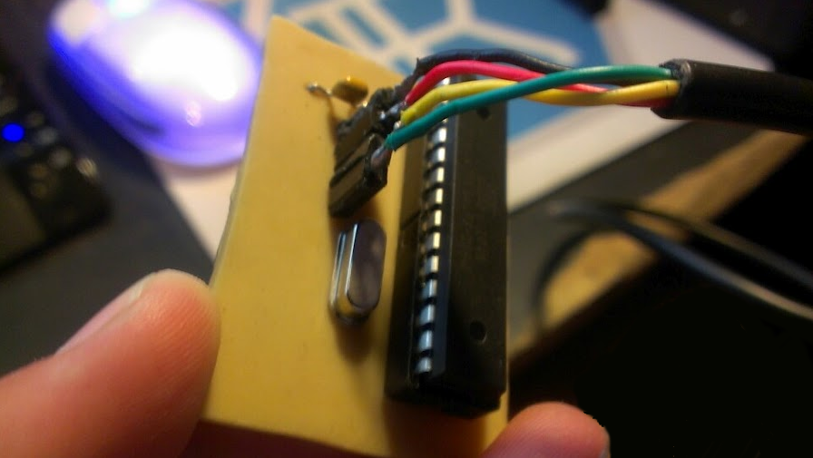
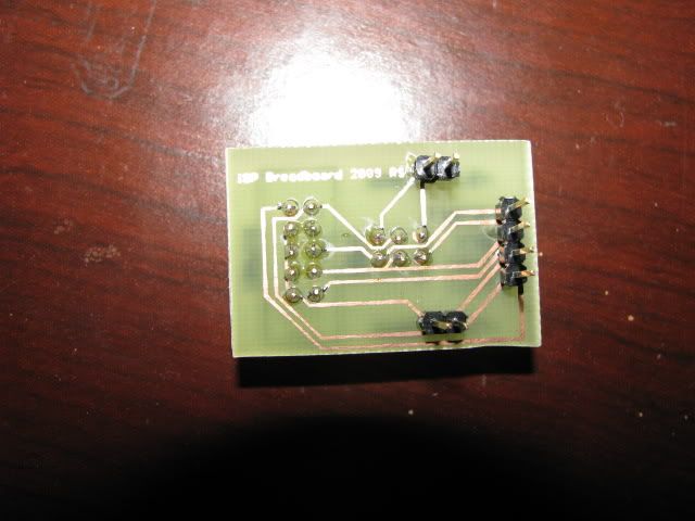
If this post looks bad, know that it is 4:30 AM and I just finished this and I'm happy and tired and aaa Annnyway, I made this PCB programmer for my nerdkits on my own :D
It was a real pain to solder though. I was getting really impatient, as my solder sucker was broken and my braided copper was too thick to work with, so I had really no way to remove the excess copper :p Isn't it beautiful?
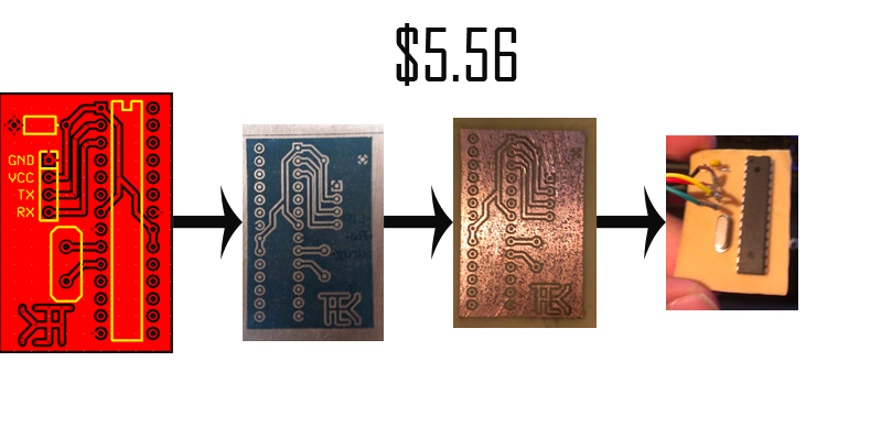
Here shows the steps I took to make it:
And as you can tell, it cost me a total of 5.56 (not including the cable/chip/capacitor/crystal) to make. I first print my design on magazine paper, and clean my copper clad board I bought from radio shack. I clean mine by scrubbing it with a scotch-brite pad until it is shiny all over. After this, I lay the design on the board, toner facing the copper. I put the copper and magazine paper into a laminating pouch, which I run through the laminator a good 7 or 8 times. Once I feel it has had enough time to melt the toner to the copper, I let it sit for about 3 minutes while it cools, then drop it a bucket of warm water for 5 or 10 minutes. I take it out of the bucket and peel away the first layer of magazine, and put it back in the bucket for a minute or two. I then proceed to rub away the rest of the paper, leaving me with what you see in the second step. After this, I let the board soak in a mixture of 1 parts 5% distilled white vinegar, to 1 parts 3% hydrogen peroxide. (You can get this at Wal-Mart for under a buck) Adding a teaspoon or so of salt really speeds things up. You will need to check on it about every 5 minutes and just rub away the green grime that builds up on the top. This is just eroded copper and nothing gross. Once your board looks a yellowish white color, you know it's done. Take it out and rub away the toner with acetone, and you are left with your design in copper (step 3 picture) Now you can proceed to drill holes and such, I use a dremel in a dremel workstation. I got some bits of various sizes as small as .4 mm from amazon for about 8 bucks. (I also broke one. :p) As you drill the holes, if you are close to the hole the drill tends to guide itself into where you want it, so being precise isn't a huge problem, but you still want to be careful. I have drilled through a trace a couple times. You will notice I have bad contrast of the copper. I forgot to turn off eco mode on my printer and was too lazy to fix it. The board works perfect though. I make my PCB designs in ExpressPCB and just print them off. No fancy tools like Eagle or anything, just plain ol' ExpressPCB. I hope you found this at least partly interesting. I had a hard time writing it with the energy I don't have. It's now 4:45 AM and I'm going to bed. c: |
|---|---|
|
August 22, 2012 by pcbolt 
|
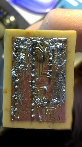
Pew - That's pretty darn good. It looks like the copper is pitted in many places...was that due to the salt? How long did the etching take? I just put together something on a flat protoboard and all the time thinking about etching a board instead. |
|
August 22, 2012 by Pew446 |
pcbolt, the copper has bad contrast (lots of holes) because I didn't use enough toner. When I rubbed away the paper I could see the bad contrast and the copper shining through, but I chose to keep it because it was my best attempt and I really wanted a working board. This is my 14th attempt at making a board. Etching takes about 30 minutes depending on how you monitor it. You should come back to it about every 5 minutes to rub off the corrosion from the salt. If you don't, the etchant can't penetrate the copper and it takes much longer. I am going to probably re purpose a fishtank bubble maker thing to make bubbles in the etchant which I hope will remove the corrosion for me. I chose to use this mixture of chemicals because I really don't want to work around any harmful fumes as with ferric chloride. |
|
August 22, 2012 by Pew446 |
I really recommend trying out PCB etching. It's really fun learning how the chemicals react with the copper and such. Plus once you're done etching you can put the chemicals on a hotplate and let it evaporate, leaving you with copper pellets you can use to plate things or maybe sell for a buck or something. |
|
August 23, 2012 by Rick_S 
|
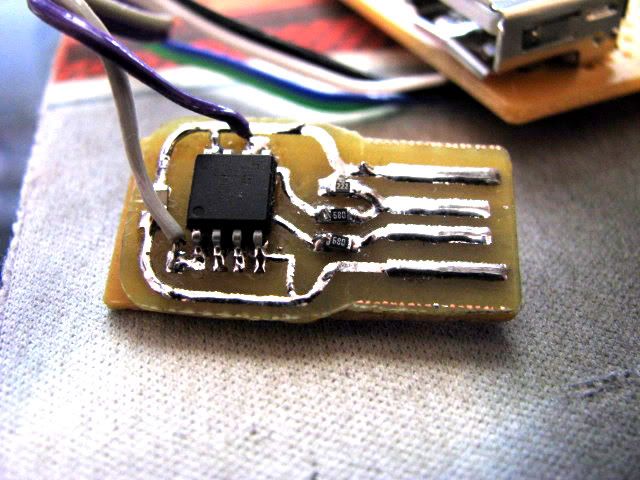
Pitting was one of the biggest problems I had with the toner method (although I used a muratic acid / hydrogen peroxide mix as an etchant). Toner is porous and unless sealed will allow some etchant through and pit the copper below. There is a film sold by a company who markets the toner method with special papers and such that will seal the toner and help prevent the pitting, but it is costly and with the cost of professionally done boards as low as it is now, not worth my money. The other problem was the amount of time it took to get a good enough transfer to etch. I guess if you did it a lot, you would get a good feel and process down, but I don't so my results were sporadic at best. Here are a couple I did... The first was a little USB prank device that emulated a USB keyboard and would periodically shift the caps lock on. The wires connected at the time were for programming only.
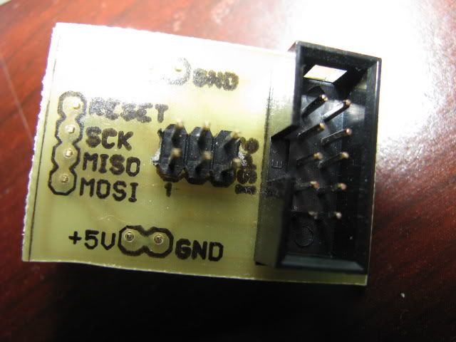
This was a little adapter board I made to plug into a breadboard to breakout the SPI connections for doing ISP programming.
I even toner transferred "silkscreened" the top of this.
Although, I will say that a home etched board does give you a strong sense of accomplishment. Good Job Pew. Rick |
|
August 23, 2012 by Ralphxyz 
|
For SPI programing do you need a crystal? Pew, can you post your schematic? Ralph |
|
August 23, 2012 by Rick_S
|
You need a crystal if the fuses have been set to use an external crystal. |
|
August 23, 2012 by Pew446 |
Here's my schematic. It's probably a lot more complicated than it needs to be, but I tend to make things that way.
|
|
August 23, 2012 by Pew446 |
Oops, just noticed I forgot to connect pin 14 to GND in my schematic. I fixed it on the board though. |
|
August 24, 2012 by Ralphxyz
|
Thanks Rick, guess I'll start a new thread regarding the crystal instead of hijacking this one :-) Ralph |
Please log in to post a reply.
|
Did you know that you can follow NerdKits on Facebook, YouTube, and Twitter? Learn more...
|


Copyright © 2013 by NerdKits, L.L.C.