NEW: Learning electronics? Ask your questions on the new Electronics Questions & Answers site hosted by CircuitLab.
Basic Electronics » How do you wire a transistor (2N7000 or 2N3904)
|
October 25, 2009 by Tug 
|
I'll start off by saying, I think I blew all my transistors by trying to learn how they work. I've seen the motor video, servo squirter video, Ipod remote control video, and a few other tutorials on YouTube. And what I got is that (1) is the drain, (2) is the gate and (3) is the source. (schematics for the 2N7000)
The source for the 2N7000 can be up to 60v. The gate can be up to 15v. In my case I am using 5v for the gate and 8v for the source. I put a LED at the drain. But it is always on. It doesn't care if the gate is High or Low. That is why I think it is blown. I tried other set ups with other transistors and I never found a "solution" where the gate would actually control the LED. Ideally I am supposed to run a solenoid (12v) with the MCU pin (2.5v?), but I am trying to get the basics down first. What am I doing wrong? |
|---|---|
|
October 25, 2009 by mrobbins (NerdKits Staff) 
|
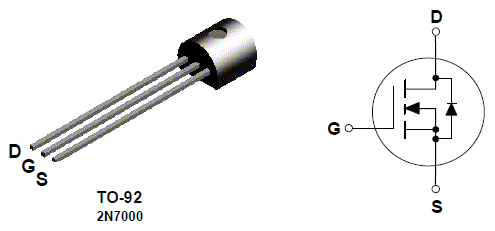
Hi Tug, Actually, you appear to have the labels for source and drain mixed up. Here's a shot from the 2N7000 datasheet:
So your #1 is actually "S" for source, #2 is "G" for gate, and #3 is "D" for drain. Because of the built-in source-drain diode, this confusion may have caused essentially all of your confusion, leading to the "always-on" situation you describe. It's "always-on" because the current is able to flow from source to drain via that diode, regardless of the gate voltage. Try swapping drain and source and see what happens. (On a breadboard this is easy: just pull out the transistor and rotate it around 180 degrees!) Also, just to be clear, it's generally best to refer to voltages as differences, as in, "The source for the 2N7000 can be up to 60V below the drain voltage." Also, the B / C / E photo refers to an NPN BJT transistor. While there are parallels between bipolar junction transistors (BJTs) and MOSFETs, I just want to make sure you treat them separately because I think you could inadvertently become confused between the two. Best, Mike |
|
October 29, 2009 by Tug
|
My bad, I put the wrong picture up. I changed it so other people wouldn't get influenced by it (and you are right it was a BJT). I got new transistors, and the first one I plugged in did the same thing..light up. I flipped the source/drain, and it is still on. My guess is I am wiring it wrong:
You can see that the gate is not even plugged in, and still lights up. Red is +9V and black 0V (9V battery). |
|
October 29, 2009 by mrobbins (NerdKits Staff)
|
Hi Tug, In the photo I'm seeing there, the source is on the left in breadboard row #6, and the drain is on the right in breadboard row #4. The source should actually be connected to ground (black). And then you probably also need to switch the pins of the LED as well. (The longer lead of the LED should be connected to +V.) Finally, with the gate "not even plugged in", anything goes -- you don't know what voltage is on the gate, which means it could be on or off. If you want to see an off-state, you really have to wire the gate to be the same as the source, i.e. ground. (And then you have to get the rest of the directions right so you don't trigger a current path through the source-drain diode.) Hope that helps! Mike |
|
October 29, 2009 by Tug
|
Thank you Mike, the common ground helped. I don't know why I didn't do this. I played a little with the gate, if you don't connect it, it really is "anything goes". But it seems to retain the position it previously had. |
|
October 29, 2009 by Tug
|
Just to double check, I had to connect the source to the negative because they are mosftet N ? And I did blow my 4 transistors. Good thing I bought 20 more. |
|
October 30, 2009 by BobaMosfet 
|
How you wire depends on the type of transistor-- what it's made of, and this determines whether it switches voltage or current. Make sure you don't put more through it on any lead than the spec sheet says it can handle, and remember those numbers are RELATIVE to one another (think how much voltage or current from all leads COMBINED). If you exceed that rating, guess what- it overheats, shorts, burns through, explodes, melts.... etc. |
Please log in to post a reply.
|
Did you know that you can connect a pushbutton to a microcontroller with only one wire? Learn more...
|


Copyright © 2013 by NerdKits, L.L.C.