NEW: Learning electronics? Ask your questions on the new Electronics Questions & Answers site hosted by CircuitLab.
Basic Electronics » Relay Question
|
February 26, 2010 by disneyd7 |
I have a reed relay with a coil amperage of 12mA and I want to actuate it with the ATmega168. The relay has a built in diode. Lets assume it is a 5 volt relay. Since the ATmega168 supports up to 40mA should I be able to put 5v to one side of the relay coil and the other side to an output on the ATmega168 and actuate it with that? Second question: My reed relay is a 12 volt relay that also has a coil current of 12mA. Can I put 12v to one side of the coil and use the ATmega168 to switch the other side to ground? Also, is the maximum current on the ATmega168 40mA total or 40mA per output? Could I connect 8 of these relays to 8 of the ATMega outputs and trigger them all at once? Thanks for any advice! BTW, What I am working towards is a system with six to eight relays that I can operate via the usb nerdkit. Any advice on the best way to hook this up is appreciated. I'm asking about the 12v relays because I already have them, but I could get 5v versions if it would be easier. |
|---|---|
|
February 26, 2010 by Rick_S 
|
The Absolute Maximum package current rating is 200mA. The Absolute Maximum current per pin is 40mA. While these low current relays could be triggered by the uC directly, my preference is not to. You definitely can not sink 12V with the uC... Bad things will happen. This is from note 3 at the end of the datasheet where it talks about current.
I'd recommend using a driver IC such as a ULN2803. This IC not only can handle the current you need with ease (500mA continuous for the package total)and has 8 outputs, it also takes a TTL input, such as that from your uC, and can sink up to 50 Volts. In effect, you isolate your uC from harms way, you can use your 12V relays, and can have them all on at the same time without any worry of uC damage. Just a thought, Rick |
|
February 26, 2010 by bretm 
|
You might think you could set a pin to output mode and set it to ground level, so it wouldn't matter that there was 12V at some other point in the circuit because at the pin it's 0V. The problem is that if you do exceed the current limit, which can easily happen briefly when switching an inductive load like a coil, the microcontroller might not be able to maintain the 0V condition at the pin. |
|
February 26, 2010 by Frozenlock |
Don't forget to use flywheel diodes with your relays, the back EMF can fries many IC components. (Yes, I learned it at my expense.) |
|
February 26, 2010 by Rick_S
|
That's where a device like the ULN2803 is so great has the diodes built in. Handles all the current need. Handles up to 50VDC devices. |
|
February 27, 2010 by disneyd7 |
Thanks for all the info so far! Can anyone explain to me how the ULN2803 works and how I would connect it to the AT168? I've read the datasheet for the ULN2803 but it isn't helping me much. Would I use the AT168 to bring a pin high on the 2803 or ground it? I'm not sure how it works (still learning). |
|
February 27, 2010 by mongo 
|
The ULN2803 is a bunch of transistors... 8 pairs of Darlington sets on a common emitter format. The output of a circuit, like the MCU can be directly connected to an input pin of the driver. the output pin of the driver connects directly to the negative (-) side of a load, like the cathode of an LED. (the straight bar). The positive side of the load (+) connects to it's supply, (The arrow side of the LED) through it's own current limiter if required. The outputs can also drive relays and other loads just as easily and if more current is required, they can be wired in parallel. Only one pin is necessary for power connection, which is a common ground termination. All 8 drivers have internal free-wheeling diodes that can be connected to the driven power source positive to control inductive kickback spikes from relay coils, etc. Otherwise, it does not need to be connected at all. The drivers are called 'current sinking' drivers because they do not supply power to their loads, rather, they provide a path to ground for a 'live' circuit already present. Hope that helps... Mongo |
|
February 27, 2010 by disneyd7 |
Ok, let me see if I have this straight... On the ULN2803: I ground pin 10. The MCU output connects to one of the input pins on the ULN2803 and when activated it provides a ground on the corresponding ULN2803 output pin which completes the circuit to operate my relay. What constitutes activating the ULN2803 input? Do I have the MCU take that pin high (5v)? I assume the 2803 needs some sort of positive voltage to work. Also, what is pin 10 on the 2803 used for? I'm not familiar with the concept of a free-wheeling diode. Thanks again! |
|
February 27, 2010 by Hexorg 
|
Um... Wouldn't just using a transistor be much easier? I remember, before I got a nerdkit, I wanted switch rotating direction of the 12V high torque motor, with an LPT port (which has only 3.3V on my old machine). So I've just stuck a PNP transistor to it, and then, connected a 12V power supply (from the wall) to power the coil in the relay and the motor itself. |
|
February 27, 2010 by Rick_S
|
Pins 1 thru 8 are your ttl level inputs. A high signal on these pins cause the corresponding output pin to go low. Pin 9 is connected to ground this would be a common ground with the 5V of your NerdKit and the 12VDC of your relays. Pin 10 is used as a common connection for the free wheeling Diodes built into the chip for each output. These act similarly to the diodes you said your relay's have built in. Per the datasheet from the Motorola version of the part: "All devices feature open–collector outputs and free wheeling clamp diodes for transient suppression." Pin 10 would usually be connected to the positive side of the voltage the chip is sinking. In your case, the +12VDC you are using to drive your relays. Hope I didn't just make things more confusing. :D Rick |
|
February 27, 2010 by mongo
|
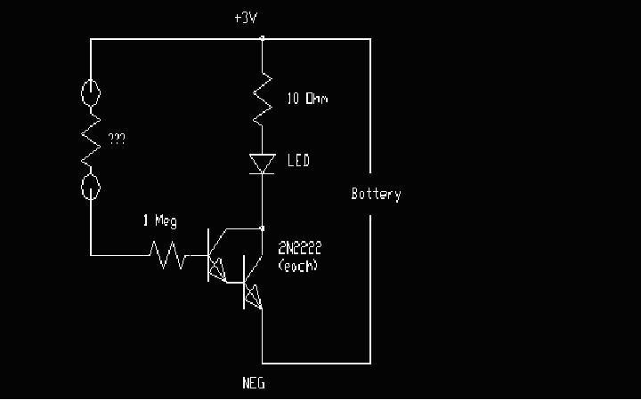
Here is a simple application on how a Darlington pair can be used.
It's a simple continuity tester. The resistor on the left is an unknown value. Insert it there and if it has any conductivity, it will light the LED. Darlington pairs have a very high gain and even your fingertip will light the LED. The ULN2803 has eight such pairs and they are great for this type of level shift. |
|
February 08, 2013 by Keith726 |
Rick_S, Mongo, I am trying to operate a large 7-segment LED, which requires 8-10 volts Vf because each segment has 4 LEDs in series. If I use ULN2803, I can switch 10 volts to each segment by using the TTL output from the MCU. Would I still hook up pin 10 to the +10V supply? I'll also have to get common-anode LED display because I will have to sink the currecnt from each segment through the ULN2803 (of course, I bought common catode LEDs - I planned to just switch the +10v to each segment using the MCU outputs - now I'll have to change the logic to sinking current instead of sourcing it to the LEDs).
In my final design, I guess I'll use a 12v wall wart, then 7805 & 7810 voltage regulators to make clean +5v and +10v. |
|
February 16, 2013 by BobaMosfet 
|
Keith726- The reason RickS suggested V+ on pin 10 is because he was saving himself using pull-ups on the output pins. Normally, since the ULN2803 is an open-collector output, you put a pull-up on each output, and connect pin 10 to ground. That way, when input goes high, the ULN2803 inverts the signal on the way to the darlington pair, causing the darling pair to not fire, allowing the pull-up to hold the output line high. If you sink the input pin on the ULN2803, the signal is inverted, the darlington-pair fires, the output pin is sunk to ground through the emitter, and the output pin goes low. If you connect it as I've suggested, you can still use your common cathode LEDs. Tie the common's together, and fire the pins using the appropriate output pins. If the LED (4 of them) require 8-10 volts, let's assume you have a 9V battery as your power-source. Simply tie the pull-up resistors on the outputs to your 9 battery ahead of the LM7805 regulator. Simply make the pull-up adequate to allow only 20mA of current through. This will allow all the current and voltage necessary to power the entire circuit. This is one of the ways in which the ULN2803 was intended to be used, allowing differing voltage supplies to be available so discrete logic could switch larger loads. BM |
|
February 17, 2013 by Rick_S
|
Wow, this is resurrecting an old thread... Actually, the connection of pin 10 to the supply voltage had nothing to do with avoiding pullups. It had more to do with enabling the built in clamping diodes in the 2803. The original thread was about driving relays. Rick |
|
February 17, 2013 by BobaMosfet
|
Rick, Interesting. How I've described it is the correct way to use any ULN2803 for controlling heavy loads with discrete logic, per the design specs. So what you're saying is confusing, given that the drawing in this thread is not accurate as to how the output pin on the ULN2803 is wired in the substrate. If anything it would appear that your method would be using the integral diodes to protect the chip against your wiring all the time, rather than for transient suppression of reverse voltage. Can you either provide a schematic of a working circuit or specifically explain exactly how your circuit is working, within the ULN2803? BM |
|
February 17, 2013 by Noter 
|
I don't see any circuit examples on the web where pin 10 is connect to GND. They all connect it to VCC. A quick check of the spec sheet also shows it also connected to VCC in the test configurations. BM, please provide a link to the design specs you refer to that show it should be connected to GND? |
|
February 17, 2013 by BobaMosfet
|
Noter-- I'm going off of Allegro's Application Notes, and their datasheets. Here is a quote from their App notes, in case you can't obtain it. Mine is hardcopy, so I typed this in- please excuse any typos. It's more eloquent than I could word it: "In the open-collector circuit the current flow is either fully on or completely shut-off. The output acts as either an open circuit (no connection to anything) or a short circuit (to ground). The transistor’s collector is typically connected to an external pull-up resistor, which sets a higher voltage to the output when the transistor is open. When any transistor connected to this resistor is turned on, the output is forced to 0 volts. Open-collector outputs are useful in many applications including summing, limiting and switching circuits. For the switching circuit, instead of outputting a signal of a specific voltage or current, a control signal is applied to the base of an internal NPN transistor whose collector is externalized (open) on a pin of the IC. The emitter of the transistor is connected internally to the ground pin. The open collector provides a pull-up resistor that does not need to be connected to a voltage at the same potential as the chip supply (Vcc). It is possible to use a lower or higher voltage. Therefore, open collector circuits are often used to interface different families of devices that have different voltage levels in their operating logic or to control external circuitry that requires a higher voltage level (for example a 12 V relay)." I've reached out to Allegro on this, because I understand what Rick has done, and why people wire it backwards-- it does actually make sense. I'm interested in finding out from Allegro if there are pros/cons for either that we haven't discussed. BM |
|
February 17, 2013 by BobaMosfet
|
Noter-- Oh, and the test configurations are logical only, on the data sheet. Almost all test configs show the clamp diode NOT connected. BM |
|
February 17, 2013 by Noter
|
Thanks BM but that doesn't help my understanding much because it doesn't say anything about the clamping diodes that are connected via pin 10 which is what I was trying to understand about your prior posts. It just looks to me that if you connect the clamping diodes to gnd via pin 10 that you will have current flowing thru them anytime there is a couple of volts or more on an output pin and the corresponding driver transistor is off. It will be interesting to see what Allegro has to say about it. |
|
February 17, 2013 by Rick_S
|
I wasn't trying to argue the use of pull-ups, I could definitely see their use. It just appears to me that the result of connecting the common to the supply line would be equivalent to a fly back on the driven element. Also virtually every example I've seen online shows it wired that way. And we all know if it's on the Internet it has to be true... :) |
|
February 18, 2013 by BobaMosfet
|
Noter- Agreed. I'm curious myself. Rick- Right, I didn't think you were arguing, just discussing. BM |
|
February 18, 2013 by Keith726 |
Gentlemen, I did not realize that resurrecting this old thread would lead to so much activity. Obviously this subject is somewhat confusing. I assure you that I have spent way too much time trying to figure out something this simple. This started by me making a clock that displays the time using only one 7-segment LED. You can see a video of the clock here http://youtu.be/FGg53Wa-_Nc. Each of the 7-segments are directly attached to 7 output pins on the MCU - it sources 5v to each segment (they have current-limiting resistors). Everything works fine with the 3/4" 7-segment common cathode LED because the voltage requirement is only a couple of volts to power each segment. I want to make a larger clock, so I bought larger, 2.3" 7-segment LEDs, and that added another level of complexity. To make the larger LED segments, the manufacturer places several LED's in series within each segment. Therefore, these larger displays require 8 volts Vf to power each segment, more than the MCU can provide. My solution - use a device like the 2803, a group of darlington transistors, as switches, each one operated by the MCU's 5v pin output to turn on a 12v supply to each LED segment. Simple! So, based on my original design which uses a 3/4" common cathode 7-segment LED (each anode is connected to the MCU pins and lit using 5v from the MCU, the cathodes are all commoned together to ground), I bought a large 2.3" Common Cathode 7-segment LED. But from what I'm reading on the Internet, and here in the forum, you are using the ULN2803 to sink current from the device to ground, not source current. That means I need to buy Common Anode LED's - the +12V will go to the common anodes and the 2803 will be connected to each cathode per segment. When I put +5v from the MCU on the input pin of the 2803 it's output pin will go to ground, allowing current to flow through that segment of the display. When there is no +5v from the MCU, the output pin will be high-z, like an open circuit. Remember, this is LED's I'm driving, not motors or coils, so I don't have to worry about the inductive issue. What do I connect the diodes to that are inside this device (+5v or GND?) I think I understand this. Is there a way to use my Common Cathode 7-segment LED display with a +12v source that can be switched with this device? In my (way too many) hours of searching this on the Internet, I also came up with ULN2003 as a suggested device for this. Thoughts? Is this a better choice for a non-inductive load? |
|
February 18, 2013 by Keith726 |
Just another thought. Can I just use a simple inverter gate to do this? If I used a CMOS 7404 chip, could I take the 5v from the MCU and then use the inverted output to ground the 12v from the 7-segment display (Common Anode)? |
|
February 19, 2013 by BobaMosfet
|
Welllllll..... I got a response back from Allegro. Here's how it's actually meant to be used (makes sense). Wire it backwards for anything that is low-impedance (like a motor or any sort of current draw), with pin 10 connected to V+. Wire it with pull-ups as I described if you're using it for voltage work only (like level shifting) with V+ connected to an output pin, and LEAVE PIN 10 DISCONNECTED. Interesting, yes? BM |
|
February 19, 2013 by Noter
|
Ok thanks, that makes sense but why do you call wiring pin 10 to V+ backwards? |
|
February 19, 2013 by BobaMosfet
|
Noter- For continuity, since I'd referred to it that way in the rest of the read. BM |
|
February 19, 2013 by Noter
|
Keith726, I guess we should get back to your questions - Since you are switching only LEDs and there is no inductive element you need not connect pin 10 (com) to anything. And you cannot use your common cathode 7seg display directly with the ULN2803 because as you have already figured out the ULN2803 can only pull a pin on the display to GND. But you don't have to use a device like the 2803, you can use PNP transistors or P-Channel mosfets to drive your common cathode display. I like VP2106 mosfets for this sort of thing. I didn't look closely at the ULN2003 but it is another open collector device that can pull pins to GND just like the ULN2803 so the same applies to it. |
Please log in to post a reply.
|
Did you know that any circuit of voltage sources and resistors can be simplified to a "Thevenin" equivalent circuit? Learn more...
|


Copyright © 2013 by NerdKits, L.L.C.