NEW: Learning electronics? Ask your questions on the new Electronics Questions & Answers site hosted by CircuitLab.
Basic Electronics » How far away can a LM34 be?
|
February 27, 2010 by Ralphxyz 
|
I "trying" to build a temperature controller. How far away could I place a LM34? I am building a solar water heater on the roof with the MCU 20 to 30 feet away. Thanks for the help, Ralph |
|---|---|
|
February 27, 2010 by mrobbins (NerdKits Staff) 
|
Hi Ralph, Take a look at these two forum posts -- I think they cover the distance issue very well: Temp sensor LM34 and The Long Arm of the NerdKit. Looking forward to seeing your water heater system controller! Mike |
|
May 13, 2010 by Ralphxyz
|
Well, I still have the same question. I have read the references a number of times. I made up a 50' CAT5 cable with the LM34 attached and got a temperature reading that is +8˚- 10˚ higher that other thermometers I have. I made up a 50' 3 wire Shielded cable and got the same 8˚ - 10˚ higher reading (with the cable coiled). I added the RC-Damper from the spec sheet and strung out the cable and now I am getting a +3˚ - 4˚ higher reading. Is the problem just that the LM34 isn't that accurate? Another thought: On page 6 of the spec sheet it says: "This is expecially true for the TO-92 plastic package, where the copper leads are the principal thermal path to carry heat into the device, so its temperature might be closer to the air temperature than to the surface temperature." So if the leads are the "principal thermal path to carry heat into the device" does this mean that the leads should not be insulated to avoid electrical shorting? Does this mean I should not do something such as this:
Thanks for the help, Ralph |
|
May 17, 2010 by carlhako |
Hi Ralphxyz I spent a while trying to work out why my lm34 was out by about 5'C the issue ended up being my source voltage. I was powering off usb which is apparently 5v, when i test it with a multimeter with the mcu running, outputting the temp to a 7segment led display it was at 4.5v. This threw the temp out. This could also be a cause check your ref voltage while the mcu is running the load may drop the voltage a bit. The LM34 is a precision temp sensor, the datasheet shows Accuracy:1°F. So this is not whats throwing your temps out. |
|
May 17, 2010 by Ralphxyz
|
I have a 15 volt power supply, probable from a PDA or possible a laptop computer that I use for my source voltage. Across the rails I have 4.94 volts. I am using the NerdKit tempsensor project. Ralph |
|
June 02, 2010 by mrobbins (NerdKits Staff)
|
Hi Ralph, Reading 3 to 4 degrees Fahrenheit too high means 30 to 40 mV too high. The very first thing to try is to use a digital multimeter that you trust to read the voltage coming back from the LM34 from the microcontroller end of the 50 foot cable. Does this multimeter also report a voltage that's 30 to 40 mV higher than what you think the actual temperature is? If so, your issue is on the thermal/LM34 sensor/cable side. If not, then it's on the ADC/microcontroller side. Then, use the same multimeter, and make the same measurement at the sensor end of the cable. Does it agree with the first measurement or not? Working backwards: If it's on the ADC/microcontroller side: there is some "offset error", but that's generally around 5-10mV or so, and 30mV would not be explained by that. There may be some scale error due to a low supply voltage. (We often see this when people run the tempsensor project with dying batteries.) Also make sure that the microcontroller pin is configured as an input and that the pull-up resistor for that pin is disabled. You might try putting a 10K resistor between the input pin and ground at the microcontroller end. If it's on the LM34 sensor / cable side: the cable shield should probably only be connected at one end, at the microcontroller. Make sure nothing else is possibly being powered / returning current through the same cable. That's because the cable is long enough that it probably has a few ohms of resistance, so a microcontroller hanging off the end of it drawing a few milliamps of current may cause a voltage drop of a few millivolts -- which your remote ADC would see as a increased sensor reading. If it's on the thermal side: you mention that this is a solar water heater, so there's both sun to heat things up, and wind to cool things down. It's probably hard to decide what the "real" temperature is to within more than a few degrees. For our Meat Thermometer video, we did try to create a relatively short thermal path using the copper braid and copper wire, but we still had to re-scale the output of the LM34 against two known points (ice water at 32F and boiling water at 212F)! Best, Mike |
|
June 02, 2010 by BobaMosfet 
|
You should add a capacitor out near your LM34, since it wasn't designed to drive loads long distances. Your conductor length is creating a reactance situation, and the capacitor will help stabilize current to the LM34. let us know what happens, please. BM |
|
June 03, 2010 by Ralphxyz
|
The shielded 50' cable has a RC Damper as illustrated in/on the spec sheet! The cable is just looped around inside my house so there isn't any wind effect. Forget the cable for the moment. I have three LM34 sensors on the bread board I have seen three to four degrees difference between the sensors which are literally right next to each other. Usually two of the sensors will be within .50˚ the other will might be 1˚ higher. Is this expectable? How would I do the boiling water test? The ice test I can place the sensor in a latex glove to keep dry but I do not know if the latex might melt at 212˚F. Could there be something in my code? The code is here . |
|
June 04, 2010 by Ralphxyz
|
Regarding my above post from May 13 what about insulating the leads? Is it best to leave them bare? If "the copper leads are the principal thermal path to carry heat into the device" how would one electrically isolate the leads? Ralph |
|
June 04, 2010 by Ralphxyz
|
I am rebuilding the 50' cable. Would this be the method to add the capacitor? This is what I had done except for the BYPASS capacitor which I'll add this time.
This is from the specsheet page 7 R-C Damper. I do not have a 70Ω resistor but I do have a 100Ω resistor which should be fine. Notice they have the shield grounded at the LM34 I always would ground the shield at the microprocessor as Mike said above. My power supply is from a portable computer so it is putting out a solid 15 volts and I have 4.95 volts across the rails so there should not be any problem with the power supply. From my post above are the illustrated temperature readings acceptable, I mean if this was your project would you accept Sensor0 at 77.08˚ and Sensor1 at 78.59˚ this is 1.51˚ difference and they are right next to each other. Anyone have any links to different temperature sensors that have been used with the ATmega168 or 328? Ralph |
|
June 04, 2010 by Ralphxyz
|
I made up a new 50' shielded cable with the LM34 temperature sensor. I used the R-C Damper configuration from the specsheet including the bypass capacitor. I did a freezing test and a boiling test. The freezing test got down to 34.5˚F the boiling test got up to 224˚F. I don't think one can go 50' with the LM34. I have a 20' CAT5 with the LM34 and that is reading 1˚ to 2˚ degrees high at room temperature. I have a 24" shielded cable with the LM34 and the R-C Damper and that is reading 3˚ - 4˚ higher then the sensors on the bread board. The two sensors I have on the breadboard are reading within a few hundredths of each other so i would assume they probable are fairly accurate or at least I could accept their readings. Any suggestion on what else to try I have seen some TWI sensors on the web maybe I'll try using TWI. Ralph |
|
June 04, 2010 by mrobbins (NerdKits Staff)
|
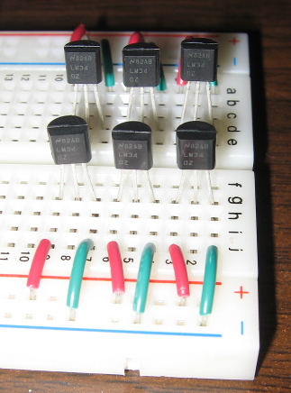
Hi Ralph, I think the problem might be that the LM34's just aren't as accurate as you desire! Almost all chip companies do "binning", where manufactured parts are tested. Those that past the strictest tests are sold for the highest price, and those with lesser performance are sold for cheaper. National Semiconductor does this with the LM34, including an "A", "CA", "C", and "D" grades. The LM34's we stock are the LM34DZ, which is the "D" grade and "Z" means the TO-92 plastic package. Take a look at this DigiKey search, which shows three grades available: the LM34DZ for $2.51 each, the LM34CZ for $6.60 each, and the LM34CAZ for $8.50 each. Huge variation in price! Now, jump to the LM34 datasheet. On pages 3 and 4, there's an accuracy listing, with "typical" and "tested limit" columns. Around room temperature, the "D" grade is listed as +/- 1.2 degrees F "typical", and +/- 3.0 degrees "tested limit". The "tested limit" means they test every single chip in a controlled environment at 77 degrees F, and if the LM34 outputs anywhere between 0.740 and 0.800 volts, it passes. Depending on what you're doing, that may be too wide a variation for your application. If you move up to the "C" grade, you get +/- 0.8 degrees typical, and +/- 2.0 degrees tested limit. And finally the "CA" grade gets you +/- 0.4 degrees typical, and +/- 1.0 degrees tested limit. So if you're willing to buy the $8.50 LM34CAZ chip, they simply promise that at 77 degrees Fahrenheit, it was tested at the factory to output somewhere between 0.760 and 0.780 volts, and will "typically" be between 0.766 and 0.774 volts. I did a little experiment here with six LM34DZ's sitting close to each other on a breadboard. Using a multimeter that reads down to millivolts, I measured the output of the six sensors:
This was on my desk, in the shade, in basically still air. Here are my six measurements, in millivolts: 762 780 771 771 774 781. From low to high, that's a range of 1.9 degrees Fahrenheit, with an average (mean) of 773 mV. While I don't know what the "true" temperature is, I can tell from these six measurements that the farthest was only 11 mV from the mean, which is only slightly worse than the "CA" bin tested limit. This seems to basically match up with the kind of variation and range you were seeing -- roughly 1.6 degree range over your three sensors, versus 1.9 degrees for mine. You may do better with the "CA" grade of LM34. However, I suspect that without calibrating each sensor individually against some known reference, and storing that calibration offset, you may not be able to do too much better even with other ICs. I further suspect that anyone who promises better results -- maybe a digital HVAC thermostat -- is probably just doing a calibration step at their factory to store an offset digitally somewhere else in their system! As for your question about the leads and insulating them: Depends on what you're trying to measure. What we did to get good thermal contact was to use one of the leads, the ground one, and solder that to the physical probe (a piece of 14 AWG solid copper wire). The probe then became part of the electrical circuit (so you may not want to do this), but it was a great way to conduct heat between the sensor and environment. Again, see the Meat Thermometer video. Using an anti-aliasing filter (i.e. a RC lowpass filter) would help prevent you from sampling high frequency noise, however might also reduce your effective resolution. To some degree, we are relying on there being a bunch of noise to average over. If the noise is reduced too far, then the signal will be "stuck" in one of the bins, so you'll be limited by the resolution of the ADC. If you are happy with the performance of the LM34 when it's close, but find that the signal transmitted over the long cable is not acceptable, then you could use one microcontroller at the sensor end of your system (on the roof?) communicating digitally to the indoor microcontroller. Hope that helps! Mike |
|
June 05, 2010 by mrobbins (NerdKits Staff)
|
Hi Ralph, Just for kicks, I took another set of measurements 18 hours later. This is in the same order as the first time. LM34DZ outputs in millivolts: It was good to see that while it's a bit cooler in my office now, all of the 6 sensor outputs experienced roughly the same change, a drop of about 18 +/- 1 millivolts. (I wouldn't expect anything better than +/- 1 millivolt because that's the resolution of my multimeter!) This tells me that at least over a span of hours, a calibration offset would remain valid. And based on the physics involved, it's reasonable to guess then that a calibration offset is probably valid for the lifetime of the device. Hopefully if someone is researching LM34 stability or temperature sensor stability and calibration, they'll find this page in the future. Mike |
|
June 06, 2010 by Ralphxyz
|
Mike, that is really fantastic and really helps my understanding of the expected accuracy. I found a cold solder joint on the R-C Damper wiring. Once I fixed the solder joint the sensor started reading in the same range as the sensors on the mother board if not a little lower so I think I will be able to "trust" the reading or at least have all of the sensors be relative. Having the sensors all within the same range is more important than actual accuracy. I do not have a "Standards" thermometer to test accuracy. While trying to do the Multi Meter test with my admittedly cheap Radio shack MM I could never get a steady reading of the sensor output. the reading would either keep on climbing or once descending way out of expected range. Using the modified Nerdkit Tempsenor project code usually the values are always jumping around but one of the sensors actually showed the same value for 5 minutes. I will keep playing around with the LM34 part of the interest is how sensitive they are. On my mother board the voltage regulator is about a inch away from the LM34s. If I increase the current load (by turning the LCD backlight on) the LM34s sense the ambient temperature rise as quickly as the voltage regulator heats up, I had to move the sensors to keep them stable. Thanks so much once again for your help. Ralph |
|
June 06, 2010 by mrobbins (NerdKits Staff)
|
Hi Ralph, Glad to be able to help. Please post your results as you continue working on your project! Mike |
|
February 14, 2012 by dcarter777 |
Thanks all who posted here. This information helped me a lot in completing a small-scale prototype for a project to move air in my old house to balance heat between rooms. One interesting thing I observed is that there is quite a bit of heat generated on the breadboard and these sensors can pick up small variations in temperature in a relatively small volume of air. When I had just two sensors in play, one on the breadboard and one on a cable about two feet away, I was getting a difference in temp readings of about five degrees. Once I got the other two sensors in play, which were also mounted on the end of about two feet of cable, the three sensors on cables agreed very closely. The cables are just 20 gauge three conductor thermostat wire and there is no RC damper on the cable. Thanks again for your posts! -dave |
Please log in to post a reply.
|
Did you know that you can see each keypress on a computer keyboard on an oscilloscope? Learn more...
|


Copyright © 2013 by NerdKits, L.L.C.