NEW: Learning electronics? Ask your questions on the new Electronics Questions & Answers site hosted by CircuitLab.
Project Help and Ideas » How to use a MOSFET to switch on another circuit - and a solar panel/battery charging question
|
May 12, 2010 by Wobbler |
Hi All, My young son and I have been working through the NerdKit and I am absolutely amazed at what we have both learnt! I guess no-one has told him that what we are doing is "hard"! (Or the instructions are really good - I suspect this is the case.) 1) Whilst learning about MOSFETs as switches, the question was asked "could we use a MOSFET to link a solar-powered LED garden lamp to a funky multi-coloured LED circuit? Would any MOSFET do or are there any power considerations? 2) The funky multi-coloured LED thing is just that - a single LED package with 3x1.5v watch cells to power it. The solar panel circuit connects to a single white LED and a 600mAh 1.2v AA cell - there is a resistor and some 4 pin package (voltage regulator?) on a small PCB in there too. We have stripped down a solar-panel lamp and mounted it in some "art" (OK, a jam jar full of glass beads, but you get the idea!) so it charges up during the day and then comes on at night. We want to swap out the funky LED with the single white one but there is the question of the voltage - should we use a larger rechargeable battery, multiple batteries or is this just impossible please? (This is all about learning components pre-major NerdKit projects. Controlling funky LEDs via NerdKit is next!) Many TIA! :o) |
|---|---|
|
May 12, 2010 by hevans (NerdKits Staff) 
|
Hi Wobbler, I'm happy to hear you are and your son are enjoying the NerdKit. If he doesn't think it is hard I suspect he is really smart! I'm not really sure what exactly your plan is for the funky LED + solar cell + mosfet, but lets see if I can answer your questions. Let's first deal with using the solar cell to power the funky LEDs. I'm not exactly sure what is going on the PCB (solar cell + white LED), but I suspect there is more than meets the eye. If you have a multimeter around, measure the voltage at the battery terminals when the light is on, then measure the voltage drop across the white LED. I suspect the resistor is in series with the LED. If you can, measure the voltage drop across both the resistor and the LED. This will give you an idea of what the circuitry in your solar cells PCB is doing, and more importantly what its ultimate output is. The next question is, assuming your little solar cell can drive the the LEDs, how are you going to use the mosfet? I can imagine a circuit where you use the mosfet as way to switch the LED on and off commanded by the NerdKit. At that point though, you might as well use the battery that is powering the NerdKit to light the LED. You also have to ask what is the microcontroller really doing in this case, is it reacting to a button push? Or maybe a temperature reading? I hope that answers more questions than it creates =). Let me know what those voltage measurements are. If you can post pictures of the solar cells PCB that would be great. I am a bit curious. Humberto |
|
May 13, 2010 by Wobbler |
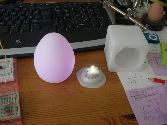
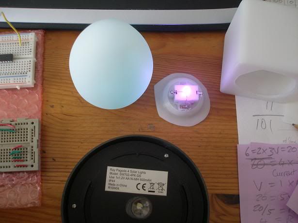
Hi Humberto, Many thanks for your response and I'll go and grab a meter shortly. Because I have a camera handy, I thought I'd use this as a test to see if I can embed images properly here - and you'll get an idea of the strange world in which your customers inhabit...
(You can see the notes from "learning" about the NerdKit too - we really had a good go at it!)
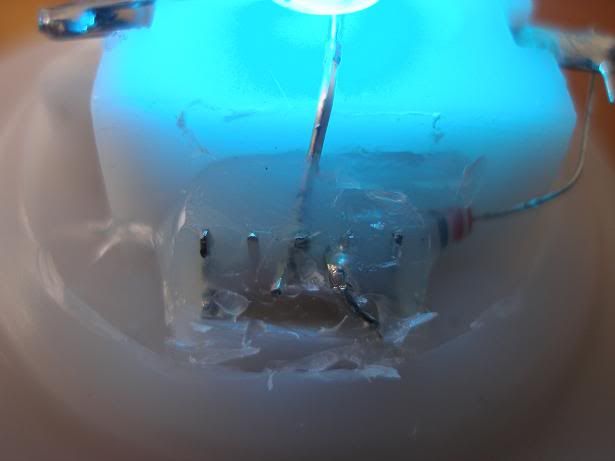
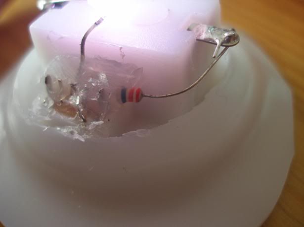
The business end from the front - a switch, an LED and a resistor!
From the side...
And from the bottom...
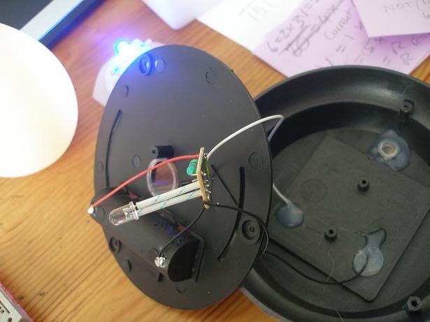
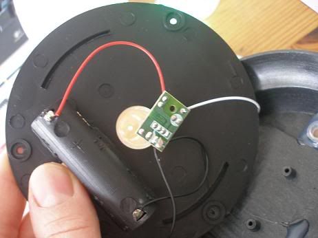
Now for the solar garden lamp - the base
And the innards - sooooo simple! Begging to be "modded"...
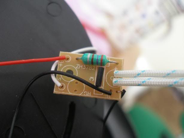
Here is the simple PCB which charges the battery during the day and lights the LED at night. Now, can we make the light more interesting than the plain white it comes with...?
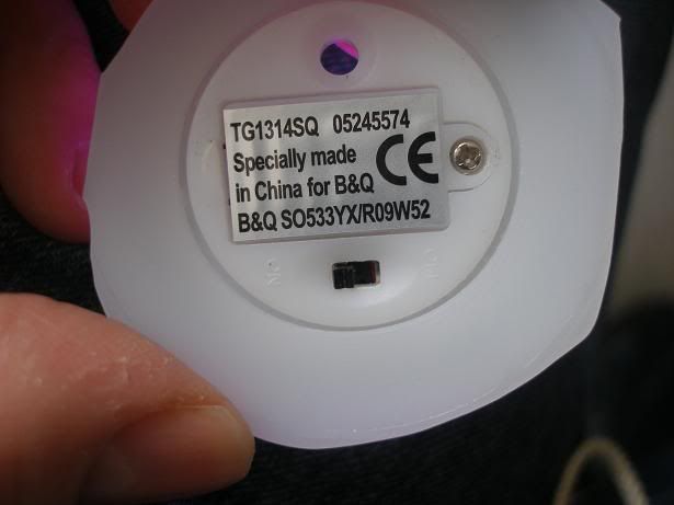
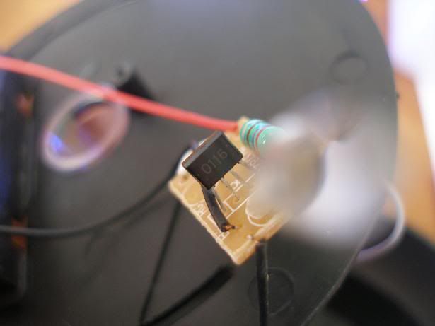
This black thing must regulate the current and do the switching - I guess... Any thoughts?
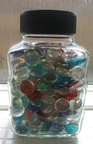
Here is one we played with - guess which is our "Objects d'Art"? ;o)
Here are the innards again - you get the idea...
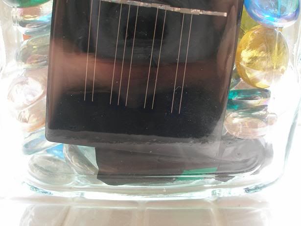
And this is the thing that lights up at night and could REALLY use some more interesting colours... :o)
So, the idea was to learn about MOSFETS by using one to switch on something - like the funky LED when the solar lamp comes on. Then, we wondered if there was a way to swap the white LED directly into the solar lamp innards - but the funky LED uses 4.5v and the solar one 1.2v... What to do? And finally, in the first picture you can see the cheeky NerdKit peeking in at the corner, wondering when we are going to finish wiring it up again to control the LEDs, and why a grown-up appears to have a rubber egg on his desk... Voltages to follow! :o) |
|
May 13, 2010 by Wobbler |
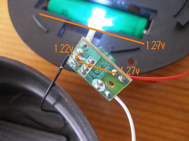
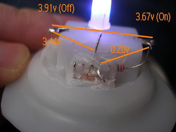
Oops! Forgot the other side of the PCB. And here are the voltages - I hope this was what you meant?
I had to take the next ones when the LED turned blue, as the voltages ranged from 3.44v to 3.67v across the LED. (3.91v off)
|
|
May 13, 2010 by hevans (NerdKits Staff)
|
Hi Wobbler, You have some pretty neat ideas here, and a couple of interesting gadgets. The funky led is probably just a an RGB LED that is being driven by a little bit of control circuitry. That is not as big of a mystery because the three 1.5V batteries which in series provide more than enough voltage to turn on an LED (somewhere around 2V). Your solar cell is a bit more peculiar because the battery is only 1.2V, a typical LED will only turn on with about 2.1V across it. I was a bit puzzled by this, so I took it to my fines electrical engineers, and after a bit of searching we found the datasheet for the IC in the board. We don't really know the details, because it is in Chinese, but we can glean enough to know that it is probably taking care of a couple of things. In conjunction with the inductor (the green thing that looks like a resistor) it is switching the voltage on and off to create voltage spikes that are large enough to turn on the LED. At the same time it also has an input for the solar cell. When there is enough voltage from the solar cell, it stops turning the LED on and starts charging the battery. When the voltage from the solar cell drops low enough (which also means it is dark outside) it starts driving the LED on. This means that your solar cell circuit will probably be able to drive the funky LEDs as long as you connect them in the same place the white LED was. Again, the mosfet doesn't really factor into this in any way I can see (perhaps I'm still not seeing what your plan is for it). A mosfet is useful as a switch when you have something that needs to be powered off a higher voltage than 5V, or requires a lot of current like a motor. A motor will need to draw a lot of current so the MCU can't drive it directly. Instead the motor is connected across the 9V power supply and the mosfet is used to switch it on an off. Let us know when you put together something neat! And of course if you have any questions. Humberto |
|
May 15, 2010 by Wobbler |
Hi Humberto, Wow! Impressed that you could find out so much so quickly! I'm also going to have to look up what an inductor is - another good learning opportunity. Is this a sort of pulse modulation type thing then? Turning the LED on and off and using persistence of vision to fill in the gaps for humans? And does that mean that the charge is being increased in the "off" phase to provide enough volts for the "on" phase? I guess I will have to experiment and find out. :o) It occurs to me that although I could plumb in another LED, the funky one may just start at Red and stay at Red, because the "off" phase will reset the colour change. Another experiment! :o) Finally, you hit the nail on the head; I had forgotten the MOSFET would run at 5v. I hadn't considered that it would need to run at the same level as the other circuits. Not to worry! We will experiment and create more "Objects d'Art" but the plan will now be to move on to the NerdKit experiments properly. Thanks again - amazing what you guys know! |
|
May 17, 2010 by carlhako |
They sell those solar lights here in australia for $1 each. amazing what you get for the price, solar panel, led, inductor, switching regulator thingo and a nicad rechargeable aaa! |
|
May 22, 2010 by Wobbler |
Post-script: The LED did indeed stay Red! The constant "reset" prevented colour change progressing. Not to worry - we have found an old fibre-optic Christmas Tree which is going to benefit! :o) Now for a new project, under NerdKit control... Bye! |
Please log in to post a reply.
|
Did you know that a thermometer can be made "faster" by using a bit of math? Learn more...
|


Copyright © 2013 by NerdKits, L.L.C.